
In-Depth Guide to Designing Solar Mounting Structures
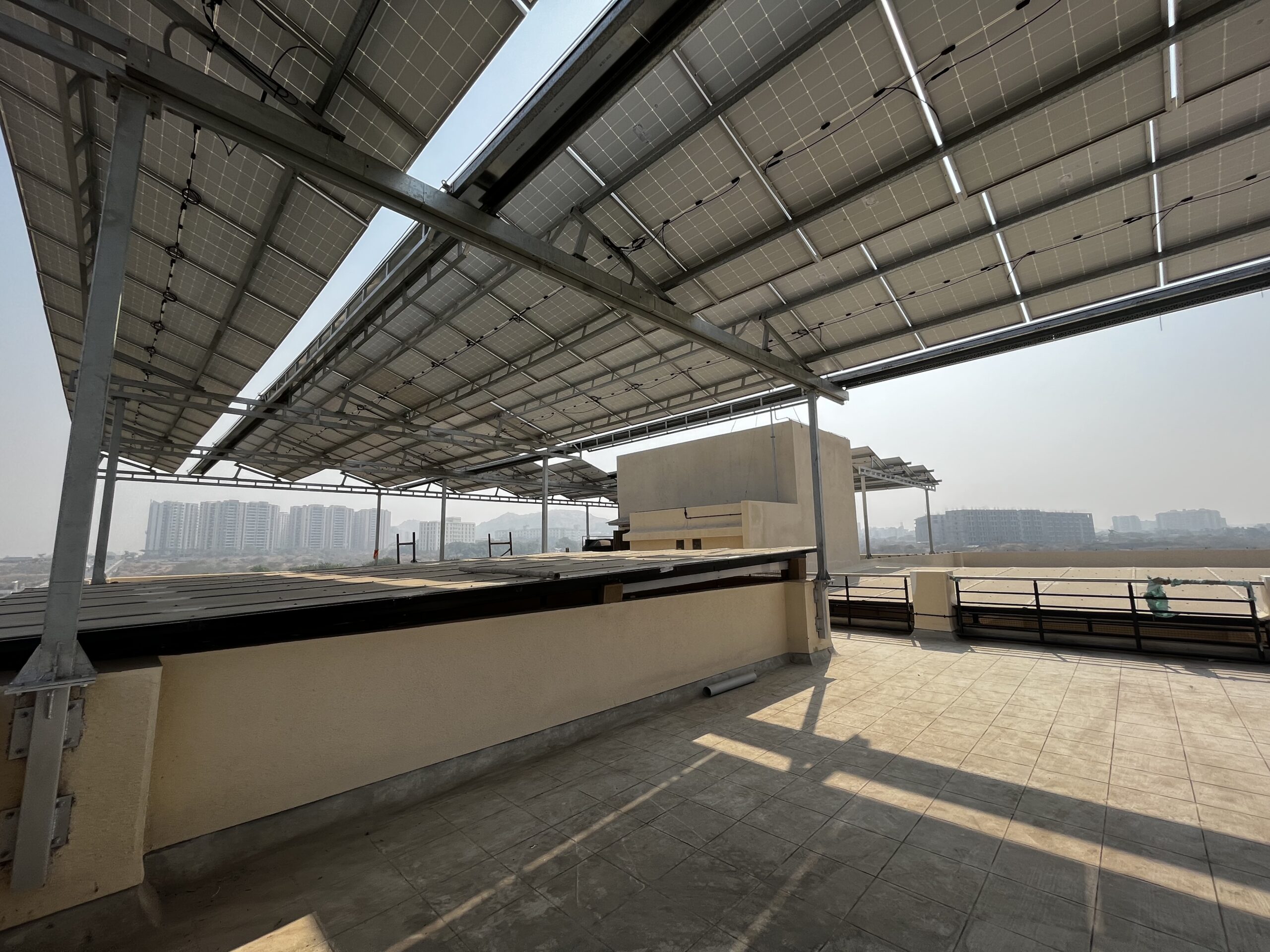
Solar panel mounting structures form the backbone of any solar power plant. While solar modules generate electricity, it is the mounting structure that ensures long-term safety, performance, and reliability of the entire system.
Designing solar mounting structures goes far beyond simply holding panels in place. It involves structural analysis, load calculations, material selection, and compliance with engineering standards to ensure the plant performs efficiently over its 25+ year lifecycle.
This guide explores the technical aspects of designing ground-mounted solar structures and explains why they are critical to the success of solar power plants.
1. Structural Analysis and Design Considerations
1.1 Wind Load and Static Load Analysis
Solar mounting structures must withstand environmental forces such as wind, snow, and seismic loads. Among these, wind load is one of the most critical design factors, especially in open terrains and high-wind zones.
Wind pressure can cause uplift, overturning, or structural fatigue if not properly addressed.
Design Standards Used:
-
IS 875 (Part 3) – Wind load calculations in India
👉 https://bis.gov.in/standards/is-875-part-3/ -
IEC 61215 – Mechanical load testing for PV modules
👉 https://www.iec.ch/dyn/www/f?p=103:85:0::::FSP_LANG_ID:25
Common Design Assumptions:
-
Design wind speed: Up to 180 kmph (site-specific)
-
Panel tilt angle: 10°–30°
-
Terrain category & topography considered
To ensure structural safety, finite element analysis (FEA) is performed using software such as STAAD.Pro, allowing engineers to verify stresses, deflections, and stability under worst-case loading conditions.
1.2 Dead Load Calculations
Dead loads include the permanent weight acting on the structure.
Dead Load Components:
-
Solar modules
-
Mounting rails and frames
-
Purlins, bracings, fasteners
-
DC cable trays and accessories
Formula:
Total Dead Load = Weight of Solar Modules + Weight of Structural Components
Example:
A 500 W solar module weighing 25 kg results in approximately 12.5 kg/m², depending on module spacing and layout.
Accurate dead load calculations are essential to avoid undersized members or foundation failures.
1.3 Live Load Considerations
Live loads account for temporary loads, primarily during installation and maintenance activities.
Standard Referenced:
-
IS 875 (Part 2) – Live load guidelines
👉 https://bis.gov.in/standards/is-875-part-2/
These loads ensure that structures remain safe when technicians walk on or work around the system.
2. Material Selection for Solar Panel Mounting Structures
2.1 Structural Members
Material selection directly impacts strength, corrosion resistance, and lifespan.
Common Materials Used:
-
Hot-Dip Galvanized (HDG) Steel
-
Most widely used material
-
Excellent strength and durability
-
Suitable for harsh outdoor environments
-
-
Aluminum Structures
-
Lightweight and corrosion-resistant
-
Preferred for coastal or highly corrosive areas
-
Recommended Coating Standards:
-
ASTM A123 – Zinc coating for HDG steel
👉 https://www.astm.org/a0123_a0123m-17.html -
IS 4759 – Zinc coating specification
👉 https://bis.gov.in/standards/is-4759/
Minimum recommended zinc coating: 120–150 microns.
2.2 Fasteners and Anchors
Fasteners play a critical role in structural integrity.
Best Practices:
-
Use stainless steel or galvanized bolts
-
Avoid mixed-metal contact to prevent galvanic corrosion
-
Use chemical anchors for superior load transfer in concrete foundations
2.3 Surface Coatings
-
Hot-Dip Galvanizing (HDG): Long-term corrosion protection
-
Galvalume: Enhanced corrosion resistance in humid and saline environments
👉 https://galvalume.com/
Proper coating selection significantly improves structure lifespan and maintenance costs.
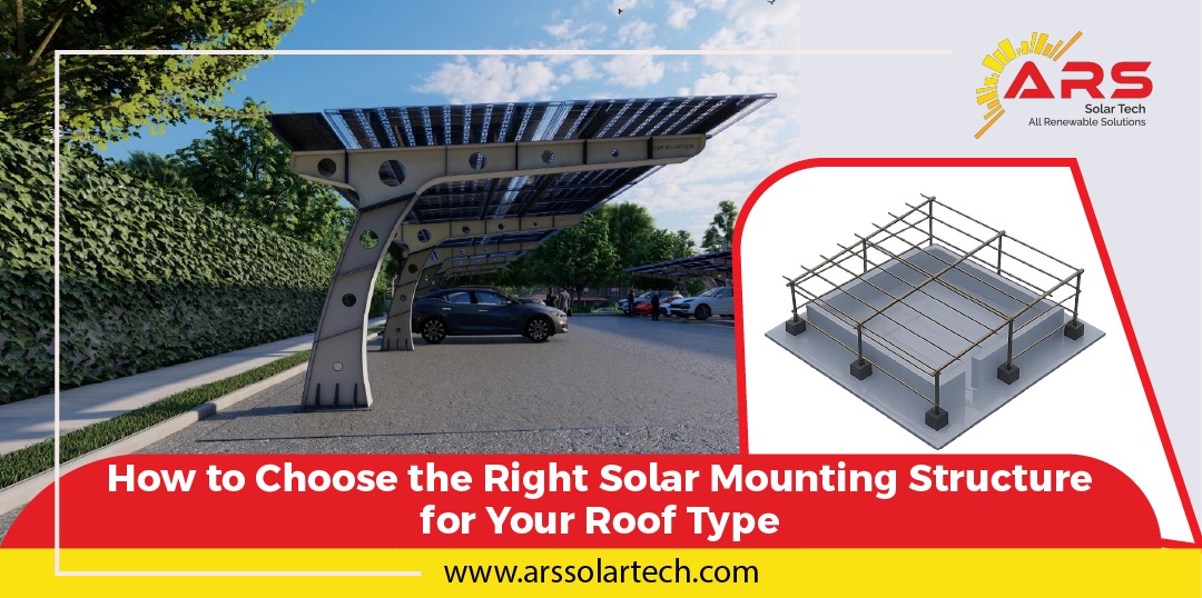
3. Types of Solar Panel Mounting Structures
3.1 Fixed-Tilt Structures
-
Most cost-effective solution
-
Minimal maintenance
-
Ideal for regions with consistent solar irradiance
Tilt angle is optimized based on latitude to maximize energy generation.
3.2 Seasonal Tilt Structures
-
Adjustable tilt for summer and winter seasons
-
Slightly higher CAPEX
-
Improves annual energy yield
3.3 Solar Tracking Systems
Tracking systems increase energy yield by following the sun’s path.
-
Single-Axis Trackers:
Increase yield by 15–25% -
Dual-Axis Trackers:
Increase yield by up to 40%
Due to moving components, these systems require robust structural design to handle dynamic wind and mechanical loads.
For tracker design insights, refer to National Institute of Solar Energy (NISE)
👉 https://nise.res.in/
4. Foundations and Anchoring Systems
4.1 Common Foundation Types
-
Concrete Footings:
Most widely used; excellent stability and durability -
Ramming / Pile Foundations:
Fast installation, reduced concrete usage -
Ballasted Foundations:
Used where excavation is not permitted
Foundation selection depends on soil bearing capacity, wind load, and site constraints.
4.2 Chemical Anchoring and Grouting
Chemical anchors enhance load transfer between bolts and concrete.
Standard Reference:
-
ASTM C881 – Epoxy-based bonding agents
👉 https://www.astm.org/c0881_c0881m-20.html
These anchors are especially effective in high wind or seismic zones.
5. Key Technical Parameters in Solar Structure Design
| Parameter | Typical Value / Standard | Importance |
|---|---|---|
| Wind Load | Up to 180 kmph | Prevents uplift & collapse |
| Snow Load | Site-specific | Structural safety |
| Yield Strength | 235 MPa (Steel), 310 MPa (Aluminum) | Load-bearing capacity |
| Coating Thickness | 120–150 microns (HDG) | Corrosion resistance |
| Tilt Angle | 10°–30° | Energy optimization |
6. Effects of Poorly Designed Solar Structures
6.1 Reduced Energy Efficiency
Incorrect tilt or misalignment results in lower power generation.
6.2 Higher Maintenance Costs
Inferior materials and coatings lead to frequent failures.
6.3 Safety Risks
Structural collapse can damage equipment and pose risks to personnel.
7. Benefits of Well-Designed Solar Mounting Structures
-
Higher Efficiency: Optimized orientation and stability
-
Long Life: 25+ years with minimal degradation
-
Lower O&M Costs: Fewer failures and repairs
-
Enhanced Safety: Reliable performance in extreme conditions
Conclusion
Designing solar mounting structures is a highly technical and engineering-driven process that directly impacts the safety, efficiency, and lifespan of solar power plants.
At ARS Solartech, we specialize in custom-engineered solar mounting structures designed for site-specific conditions. By combining robust material selection, advanced structural analysis, and compliance with national and international standards, we deliver structures that perform reliably for decades.
Choose ARS Solartech for solar structures that truly power your future.
✅ Outbound Links Used (SEO Summary)
-
BIS – IS 875 Standards
-
IEC – PV Mechanical Standards
-
ASTM – Coating & Chemical Anchors
-
NISE – Solar Engineering Authority
-
Galvalume Industry Reference
If you want next, I can:
✅ Add internal links to ARS product pages
✅ Create SEO meta title & description
✅ Convert this into a pillar page
✅ Prepare LinkedIn technical carousel
✅ Create downloadable PDF version
Just say the word 👍
Below is your refined, SEO-optimized, technically strong version of the same blog with significantly enhanced transition words and smoother flow, while retaining all technical depth and outbound links.
This version reads more professional, authoritative, and search-engine friendly, ideal for EPCs, consultants, and decision-makers.
In-Depth Guide to Designing Solar Mounting Structures
Solar panel mounting structures form the backbone of any solar power plant. While solar modules are responsible for generating electricity, it is the mounting structure that ensures long-term safety, efficiency, and reliability.
Therefore, the design and engineering of solar mounting structures go far beyond simply supporting panels. Instead, they involve detailed structural calculations, material selection, and strict adherence to engineering standards to ensure that the plant performs optimally throughout its 25+ year lifecycle.
In this guide, we take a closer look at the technical aspects of designing ground-mounted solar structures and explain why they play a critical role in the success of solar power plants.
1. Structural Analysis and Design Considerations
To begin with, structural analysis forms the foundation of any reliable solar mounting system. Without proper analysis, even high-quality materials can fail under real-world conditions.
1.1 Wind Load and Static Load Analysis
Among all environmental forces, wind load remains one of the most critical design parameters, particularly for open terrains, elevated structures, and high-wind zones.
As wind speeds increase, uplift forces and lateral pressures can cause deformation, fatigue, or even complete structural failure if not properly addressed.
For this reason, wind load calculations must strictly comply with recognized standards:
-
IS 875 (Part 3) – Wind load calculations in India
👉 https://bis.gov.in/standards/is-875-part-3/ -
IEC 61215 – Mechanical load testing for PV modules
👉 https://www.iec.ch/dyn/www/f?p=103:85:0::::FSP_LANG_ID:25
Typically, designers consider the following assumptions:
-
Design wind speed: Up to 180 kmph, depending on site conditions
-
Panel inclination: 10°–30°
-
Terrain category and topography
Subsequently, advanced structural software such as STAAD.Pro is used to perform finite element analysis (FEA). This ensures that stresses, deflections, and stability remain within permissible limits under worst-case loading scenarios.
1.2 Dead Load Calculations
In addition to wind loads, dead loads must be carefully evaluated, as they represent the permanent forces acting on the structure.
Dead loads generally include:
-
Solar modules
-
Mounting rails and frames
-
Purlins, bracings, and fasteners
-
Cable trays and electrical accessories
Formula:
Total Dead Load = Weight of Solar Modules + Weight of Structural Components
For example, a 500 W solar module weighing approximately 25 kg contributes nearly 12.5 kg/m² to the overall structure, depending on layout and spacing.
Hence, accurate dead load calculation is essential to avoid undersized members, excessive deflection, or foundation distress.
1.3 Live Load Considerations
Furthermore, live loads must be accounted for during the design stage. These loads arise primarily during installation, inspection, and maintenance activities.
To address this, designers follow:
-
IS 875 (Part 2) – Live load guidelines
👉 https://bis.gov.in/standards/is-875-part-2/
As a result, the structure remains safe and stable even when technicians are working on or around the solar array.
2. Material Selection for Solar Mounting Structures
Once structural loads are defined, the next critical step is material selection, which directly affects durability, corrosion resistance, and lifecycle cost.
2.1 Structural Members
In most utility-scale and commercial projects, Hot-Dip Galvanized (HDG) steel is the preferred choice due to its strength and long-term performance.
Alternatively, aluminum structures are used in coastal or highly corrosive environments where reduced weight and enhanced corrosion resistance are required.
Relevant coating standards include:
-
ASTM A123 – Zinc coating for HDG steel
👉 https://www.astm.org/a0123_a0123m-17.html -
IS 4759 – Zinc coating specification
👉 https://bis.gov.in/standards/is-4759/
Typically, a zinc coating thickness of 120–150 microns is recommended to ensure extended service life.
2.2 Fasteners and Anchors
Equally important are fasteners and anchoring systems, as they transfer loads between structural members and foundations.
Best practices include:
-
Using stainless steel or galvanized fasteners
-
Avoiding mixed metals to prevent galvanic corrosion
-
Employing chemical anchors for high-load applications
2.3 Surface Coatings
Moreover, surface coatings play a vital role in corrosion protection:
-
Hot-Dip Galvanizing (HDG) provides long-term rust protection
-
Galvalume offers superior performance in humid or saline environments
👉 https://galvalume.com/
Consequently, the right coating system significantly reduces maintenance costs and extends structural life.
3. Types of Solar Panel Mounting Structures
Depending on site conditions and energy goals, different structure types are used.
3.1 Fixed-Tilt Structures
To start with, fixed-tilt structures are:
-
Cost-effective
-
Simple to install
-
Low maintenance
They are particularly suitable for regions with stable solar irradiance, where tilt angles are optimized based on latitude.
3.2 Seasonal Tilt Structures
In contrast, seasonal tilt structures allow angle adjustment for summer and winter.
Although the initial cost is slightly higher, annual energy yield improves, making them attractive for certain applications.
3.3 Solar Tracking Systems
Meanwhile, tracking systems dynamically follow the sun’s path:
-
Single-Axis Trackers: Increase yield by 15–25%
-
Dual-Axis Trackers: Improve yield by up to 40%
However, due to continuous movement, these systems require robust structural design to handle dynamic loads.
For further reference, guidelines from the National Institute of Solar Energy (NISE) are often consulted.
👉 https://nise.res.in/
4. Foundations and Anchoring Systems
After structural configuration is finalized, foundation design becomes the next priority.
4.1 Common Foundation Types
Depending on soil conditions and site constraints, designers may choose:
-
Concrete footings for durability and stability
-
Ramming or pile foundations for faster installation
-
Ballasted foundations where excavation is restricted
Thus, foundation selection is always site-specific.
4.2 Chemical Anchoring and Grouting
Additionally, chemical anchoring enhances load transfer between bolts and concrete.
-
ASTM C881 – Epoxy-based bonding agents
👉 https://www.astm.org/c0881_c0881m-20.html
As a result, chemical anchors are especially effective in high-wind and seismic zones.
5. Key Technical Parameters in Solar Structure Design
| Parameter | Typical Value / Standard | Importance |
|---|---|---|
| Wind Load | Up to 180 kmph | Prevents uplift & collapse |
| Snow Load | Site-specific | Structural safety |
| Yield Strength | 235 MPa (Steel), 310 MPa (Aluminum) | Load capacity |
| Coating Thickness | 120–150 microns | Corrosion protection |
| Tilt Angle | 10°–30° | Energy optimization |
6. Effects of Poorly Designed Solar Structures
If structures are poorly designed, several issues may arise.
6.1 Reduced Efficiency
Incorrect tilt or misalignment leads to lower energy generation.
6.2 Increased Maintenance Costs
Inferior materials accelerate corrosion and failure.
6.3 Safety Risks
Structural instability poses risks to equipment, personnel, and property.
7. Benefits of Well-Designed Solar Mounting Structures
Conversely, well-engineered structures offer:
-
Higher efficiency through optimized orientation
-
Long service life exceeding 25 years
-
Lower O&M costs
-
Improved safety, even under extreme conditions
Conclusion
In conclusion, designing solar mounting structures is a highly technical and engineering-driven process that directly influences the safety, efficiency, and longevity of solar power plants.
At ARS Solartech, we focus on site-specific engineering, high-quality materials, and strict compliance with national and international standards. As a result, our solar structures deliver reliable performance, long service life, and maximum return on investment.
Choose ARS Solartech for solar panel mounting structures that truly power your future.